
A look inside the cell
Where an investigation could begin.
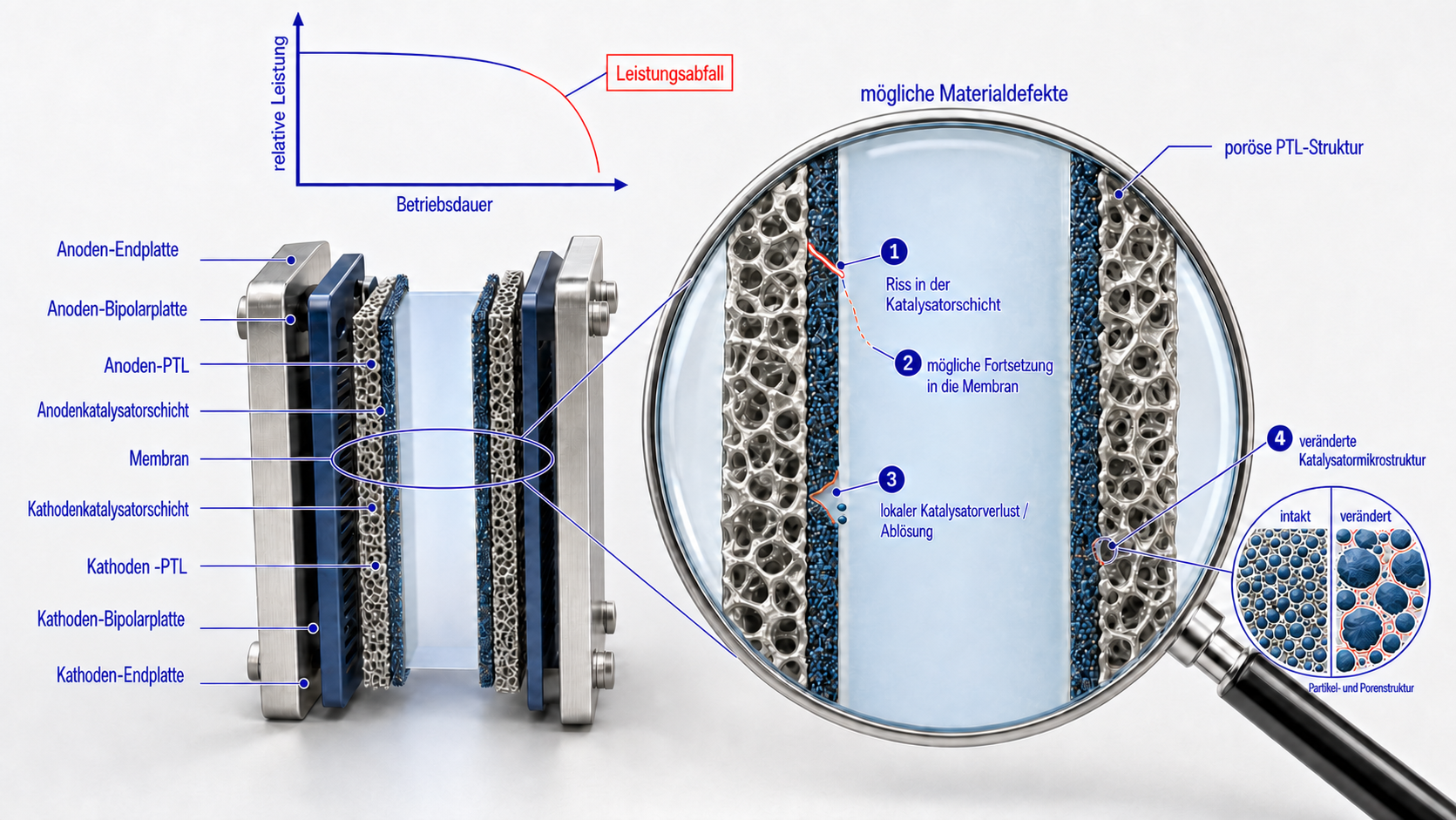
Using PEM electrolysis as an example, the magnified view illustrates possible changes within layers and at their interfaces.
The four callouts
The schematic shows an electrolysis cell with a proton exchange membrane (PEM). The outer plates surround porous transport layers (PTLs), catalyst layers and the membrane. The labels in the original image are in German. The four numbered callouts illustrate possible material changes:
- Catalyst-layer cracks: the layer may be locally interrupted.
- Possible extension into the membrane: the dashed line indicates possible crack propagation.
- Local catalyst loss or detachment: material may be missing or separate from the adjacent layer.
- Changes in catalyst microstructure: the distribution of particles and pores may change.
The performance curve is schematic. Whether and how such changes affect performance needs to be assessed together with measurement data and the history of the specific sample.
Open the original image to zoom in ↗
Discuss your development question ↗